

30公斤40公斤50公斤
30公斤40公斤50公斤
30公斤40公斤50公斤
30公斤40公斤50公斤
30公斤40公斤50公斤
30公斤40公斤50公斤
30公斤40公斤50公斤
30公斤40公斤50公斤
30公斤40公斤50公斤
30公斤40公斤50公斤
30公斤40公斤50公斤
企业名:特裕电子(深圳)有限公司
类型:贸易/代理/分销
电话: 18718484368
手机:18718484368
联系人:陆经理
QQ: 
微信:
邮箱:dishiaa@163.com
地址:广东深圳南山区粤海街道高新社区高新南七道138号惠恒大楼一期394
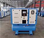
螺杆空压机
Screw Air Compressor
使
用
手
册
User Manual
安装使用前请详细阅读说明书
Please read the instructions before installation and use.
感谢您选用螺杆空气压缩机!
本公司对产品享有设计变更权,不负责对已出厂产品进行相应修改和改进之义务。以后可能会对某些产品的规格或零部件作修改,恕不另行通知。
![]()
说明:1、如不特别指明,本说明书中所指的压力均为表压力;
2、用户就保养、服务等有关压缩机的问题与本公司联系时请提供以下几项:
①、机械编号:
②、机头编号:
③、电机铭牌:
④、故障更换配件图片:
⑤、开机调试日期:
![]()
目 录
一.空压机安装细则 PAGEREF _Toc226164256 \h 1
1.1安装 PAGEREF _Toc226164257 \h 3
1.2配管、基础及冷却系统注意事项 PAGEREF _Toc226164257 \h 3
1.3电器一般规范及安全规范 PAGEREF _Toc226164257 \h 3
二.螺杆空压机的工作原理及优缺点 PAGEREF _Toc226164256 \h 1
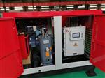
2.1螺杆压缩机的基本结构 PAGEREF _Toc226164257 \h 3
2.2工作原理 PAGEREF _Toc226164258 \h 3
2.3螺杆压缩机的优点 PAGEREF _Toc226164259 \h 5
2.4螺杆压缩机的缺点 PAGEREF _Toc226164260 \h 5
三.操作过程中的安全措施 PAGEREF _Toc226164261 \h 6
3.1一般预防措施 PAGEREF _Toc226164262 \h 6
3.2操作过程中的预防措施 PAGEREF _Toc226164263 \h 6
3.3保养或维修过程中的预防措施 PAGEREF _Toc226164264 \h 7
四.操作工程中的维护保养 PAGEREF _Toc226164265 \h 8
4.1预防维修计划 8
4.2.换油 8
4.3.更换油滤器 8
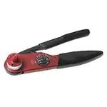
4.4.空气过滤器的维护与保养 8
五.保养 9
5.1预防维修计划 9
5.2换油 PAGEREF _Toc226164272 \h 9
5.3更换滤油器 PAGEREF _Toc226164273 \h 10
5.4空气过滤器的维护与保养 PAGEREF _Toc226164274 \h 10
六.故障排除 10
6.1故障排除表 10
6.2螺杆压缩机一般换油程序 10
空压机安装细则
通常所称的螺杆压缩机即指双螺杆压缩机。在压缩机的机体中,平行地配置着一对相互啮合的螺旋形转子。


通常把节圆外具有凸齿的转子,称为阳转子或阳螺杆。把节圆内具有凹齿的转子,称为阴转子或阴螺杆。一般阳转子与原电动机连接,由阳转子带动阴转子转动。转子上的一对轴承实现轴向定位,并承受压缩机中的轴向力。转子两端的圆柱滚子轴承使转子实现径向定位,并承受压缩机中的径向力。
在压缩机机体的两端,分别开设一定形状和大小的孔口。一个供吸气用,称为进气口;另一个供排气用,称作排气口。
螺杆压缩机的工作循环可分为吸气、封闭和输送 、压缩及排气四个环节。随着转子旋转,每对相互啮合的齿相继完成相同的工作循环。

转子转动时,阴阳转子的齿沟空间在转至进气端壁开口时,其空间,此时转子齿沟空间与进气口的相通,因在排气时齿沟内的气体被完全排出,排气完成时,齿沟处于真空状态,当转至进气口时,外界气体即被吸入,沿轴向进入阴阳转子的齿沟内。当气体充满了整个齿沟时,转子进气侧端面转离机壳进气口,在齿沟的气体即被封闭。
啮合面与排气口之间的齿沟空间逐渐变小,齿沟内的气体被压缩使压力提高。
当转子的啮合端面转到与机壳排气口相通时,被压缩的气体开始排出,直至齿尖与齿沟的啮合面移至排气端面,此时阴阳转子的啮合面与机壳排气口的齿沟空间为0,即完成排气过程,在此同时转子的啮合面与机壳进气口之间的齿沟长度又达到长,进气过程又再进行。
从上述工作原理可以看出,螺杆压缩机是一种工作容积作回转运动的容积式气体压缩机械。气体的压缩依靠容积的变化来实现,而容积的变化又是借助压缩机的一对转子在机壳内作回转运动来达到。
2.3.2操作维护方便:操作人员不必经过培训,可实现无人值守运转。
2.3.3动力平衡性好:螺杆压缩机没有不平衡惯性力,机器可平稳地高速工作,可实现无基础运转。
2.3.4适应性强:螺杆压缩机具有强制输气的特点,排气量几乎不受排气压力的影响,在宽广范围内能保证较高的效率。
2.3.5多相混输:螺杆压缩机的转子齿面实际上留有间隙,因而能耐液体冲击,可压送含液气体,含粉尘气体,易聚合气体等。
2.4螺杆压缩机的缺点
螺杆压缩机的转子齿面是一空间曲面,需利用特制的刀具,在价格昂贵的专用设备上进行加工。另外,对螺杆压缩机气缸的加工精度也有较高的要求。
由于受到转子刚度和轴承寿命等方面的限制,螺杆压缩机只能适用于中,低压范围,排气压力一般不能超过3.0Mpa。
螺杆压缩机依靠间隙密封气体,目前一般只有容积流量大于0.2m3/min,螺杆压缩机才具有优越的性能。
3.1.1请勿把玩压缩空气。请不要让空气接触您的皮肤或者将气流对着人。请勿使用压缩空气为衣服除尘。使用压缩空气清洁设备时,务必小心并佩戴防护眼镜。
3.1.2操作人员必须遵循安全操作规则,并遵守当地所有相关的工作安全要求及规定。
3.1.3安装、操作、保养和维修工作只能有经过授权认可的训练有素的人员执行。
3.1.4压缩机产生的空气不视为可达到呼吸质量。
3.1.5进行任何保养、维修、调节或其它任何非常规检查之前,请停止运行压缩机,按下紧急停机按钮,切断电源并为压缩机降压。此外,必须打开和锁定电源隔离开关。
3.2.1打开远程控制机器电源的人员应采取足够的预防措施,以确保没有人员在检查或操作该机器。因此,应当在远程起动设备上粘贴相应的通知。
3.2.2使用正确软管和管接头的类型和尺寸进行连接。通过软管或空气管路排气时请确保安全地固定好开口端。如果随意放置开口端,开口端将会突然移动,并可能造成伤害。在断开软管连接前,请确保软管已完全降压。
3.2.3请勿在可能吸入易燃或有毒的气体、蒸汽或颗粒时运行机器。
3.2.4请勿低于或高于额定限值运行机器。
3.2.5运行过程中保持箱体的所有门都关闭。只有在执行常规检查等操作时,才能将这些门打开一会儿。打开机门时,请戴好护耳器。
3.2.6待在声压级达到或超过90分贝的环境或房屋内的人员应当佩戴护耳器。
3.2.7请定期检查:
3.2.7.1所有保护装置均安装到位,并已安全固定。
3.2.7.2机器内的所有软管和管道均状况良好、安全可靠并无磨损。
3.2.7.3没有泄露。
3.2.7.4使用超2000小时,所有紧固件包括电线均要定时旋紧。
3.2.7.5所有电引线均安全。
3.2.7.6安全阀和其他压力释放装置没有被污垢或涂料阻塞。
3.2.7.7空气出口阀门和空气管网(即管道、联轴器、歧管、阀门、软管等)均经过良好维修,没有出现磨损或滥用现象。
3.2.8请勿拆卸或篡改机器上安装的安全装置、保护装置或绝缘体。
3. 2. 9 请在机器停止运行时间超过8小时后,重开机时要注意油气桶内的冷凝水。
3.3.1始终佩戴防护眼镜。
3.3.2使用正确的工具执行保养和维修工作。
3.3.3使用原装备用零件。
3.3.4所有保养工作应当只在机器已经冷却无压力时进行。
3.3.5应当在起动设备上粘贴有诸如“正在工作;请勿起动”字样的警告标记。
3.3.6打开远程控制机器电源的人员应采取足够的预防措施,以确保没有人员在检查或操作该机器。
3.3.7在连接或断开管道之前,先关闭压缩机空气出口阀门。
3.3.8在拆卸任何加压的构件之前,先将机器与所有压力源有效地隔离开来,并释放整个压力系统。
3.3.9请勿使用易燃溶剂或四氯化碳清洁零件。请采取安全措施以防范清洁液发出的有毒气体。
3.3.10保养和维修时,仔细查看机器的清洁情况。在零件和敞口上盖上一块干净的布、纸或胶带,以防沾上灰尘。
3.3.11请勿在润滑油系统附近进行焊接或执行其他任何会发热的操作。
3.3.12无论何时,只要有迹象表明或怀疑机器的某个内部零件过热,就应当停止运行该机器,但必须在经过足够的冷却时间之后才打开检查盖,这样可以避免在空气进入时油蒸汽发生自燃的风险。
3.3.13请勿使用明火火源来检查机器、压力容器等的内部。
3.3.14确保机器内或机器上没有遗留任何工具、松动的零件或抹布。
3.3.15应定期对所有调节和安全装置进行保养,以确保它们能正常工作。这些装置不能出现故障。
3.3.16每次更换分离器滤芯时,请检查排放管和油气分离器容器内部的积碳情况;如果积碳过多,则应当清除。
3.3.17应保护电动机、空气过滤器、电子元件和调节构件等,以防水分进入,例如,在进行蒸汽清洗时,除锈清洗等。
3.3.18确保所有隔音材料(例如,箱体上以及压缩机的空气进口和出口系统中的此类材料)的状况良好。如有损坏,请用制造商提供的原装材料更换,以防声压级上升。
3.3.19请勿使用可损坏空气管网材料(例如,聚碳酸酯底座)的腐蚀性溶剂。
3.3.20在处理冷却液时,请特别注意以下安全措施:
3.3.20.1请勿吸入冷却液蒸汽。请检查工作区是否通风良好;如有必要,请使用呼吸防护工具。
3.3.20.2始终佩戴专用手套。如果冷却液接触到皮肤,请用水冲洗皮肤。如果液态冷却液透过衣服接触到皮肤,请不要匆匆脱掉或除下衣服,而应该用大量淡水冲洗衣服,直至冲走所有的冷却液,然后寻求医疗急救。
3.3.21保护双手,以防止接触到滚烫的机器零件而受伤,例如在排油过程中。
在执行保养、维修或调整之前,请执行以下操作:
?停止运行压缩机。
?按紧急停机按钮。
?关闭空气出口阀门,打开冷凝水手动排污阀。
?对于配备了电子排污的压缩机,请按电子排污顶部的测试按钮,直至储气罐和出口阀之间的空气系统充分降压。
?切断电源。
?打开并锁定隔离开关。
4.1.1注意
?只可使用经厂家授权认可的零部件。
?任何因使用未经厂家授权认可的零部件而导致损坏或故障,厂家将不予保修。
4.1.2常规信息
维护保养时,请更换所有拆卸的垫片、O型圈和垫圈。
4.1.3预防性保养计划
4.1.3.1每班检查显示屏上的读数。
4.1.3.2每班加载过程前请检查是否排放冷凝水。
4.1.3.3每班检查油位。起动之前,油位应该在油位镜上方红线外。
4.1.3.4每三个月(500小时)清洁压缩机。
4.1.3.5每三个月(500小时)检查可能出现的泄露。
4.1.3.6每三个月(500小时)检查冷却器;如有必要,请清洁冷却器。
4.1.3.7每三个月或(3000小时)所有电路要加紧一遍。
4.1..8耗材报警时,根据显示的保养计划执行保养操作。
4.2.1运行压缩机,直至变热。停止运行压缩机,关闭空气出口阀门并切断电源。请等待几分钟,然后将加油口螺塞旋松一圈,释放系统中的压力,已达到降压的目的。
4.2.2旋松油冷却器顶部的放油堵头。
4.2.3取下放油塞放油。以下构件上装有放油塞:
?储气罐
?断油阀
?单向阀
?齿轮箱
?油冷却器。
?水冷却器。
4.2.4放油塞或泄油阀旋紧关闭,取下加油螺塞。向油气桶中加入油,直至油位到达观油镜四分之三处。重新装好并旋紧加油口螺塞,取出空滤总成,向进气阀进气口处添加适量冷却液。
4.2.5加载运行压缩机几分钟(有温控阀时,需温度达到90℃),在查看运行油位是否在二条红线中间处。
4.2.6如油位不够时,将加油口螺塞旋松一圈以释放系统中的压力,从而为系统降压。拆下螺塞。向油气桶中加入油,直至油位到达油镜三分之二。旋紧加油螺塞。
4.2.7在执行相关“保养计划”中的所有保养操作后,请按如下所述复位保养报警:
?进入用户参数→维护参数,把所更换的耗材复位至“0”
?首次保养后需进入使用时间预置参数,将所有耗材时间调整2500H。
4.3.1停止运行压缩机,关闭空气出口阀门并切断电源。请等待几分钟,然后将加油口螺塞旋松一圈,释放系统中的压力,以达到降压的目的。
4.3.2使用油盘以避免可能出现的油溢出。将油过滤器旋松一圈并等待几分钟,让过滤器中的油流入油气桶。再拆卸油过滤器。
4.3.3清洁多过滤器底座。为新过滤器的垫片抹油,并将过滤器旋至适当位置,直到垫片接触到底座。然后手动旋紧。
4.3.4旋紧螺塞。
空气滤清器是滤除空气尘埃污物的部件,过滤后的干净空气进入螺杆转子压缩腔压缩。因螺杆机内部间隙只允许15u以内的颗粒滤出。如果空滤芯堵塞破损,大量大于15u的颗粒物进入螺杆机内循环,不仅大大缩短机油滤芯、油细分离芯的使用寿命,还会导致大量颗粒物直接进入轴承腔,加速轴承磨损使转子间隙增大,压缩效率降低,甚至转子枯燥咬死。
4.4.1空滤芯每星期清理,拧开空滤压盖帽母,取出空滤芯,用0.2-0.4Mpa的压缩空气,从空滤芯内腔向外吹除在空滤芯外表面的尘埃颗粒,用干净的抹布将空滤壳内壁上的赃物擦干净。回装空滤芯,注意空滤芯前端部的密封圈要与空滤壳内端面贴合严密。柴油动力螺杆机的柴油机进气空滤芯的保养应与空压机空滤芯同步进行,保养方法相同。
4.4.2空滤芯正常情况1000-1500小时更换,环境特别恶劣的使用场所,如矿山、陶瓷厂、棉纺厂等,建议每500小时更换空气滤芯。
4.4.3清洁或更换空滤芯时,部件是必须一一合对,严防异物落入进气阀。
4.4.4平时须经常检查进气伸缩管有无破损、吸扁,伸缩管与空滤进气阀的连接口有无松动、漏气。如发现须及时修复、更换。
5.故障排除表
项目 |
故障情形 |
可能发生原因 |
排除原因 |
(一) | 无法启动 (电流不平衡或失相) | 1、三相电压是否平衡 2、检查互感器线是否接 触不良 3、拆掉电机主线,在开机时用表测量接触器输出电压是否跟进电值一致 4、电机故障 5、控制器检测有问题 | 1、请维护人员检修更换 2、请维护人员检修更换
3、请维护人员检修更换
4、请维护人员检修更换 5、检查电源及各接点
|
(二) | 运转时电流过高,报故障 | 1、电压太低 2、压力过高
3、油气分离器堵塞 4、压缩机本体故障(电机或机头) | 1、请维护人员检修 2、控制器压力设置,如设置过高需重新调整 3、更换油气分离器 4、请联络公司服务单位
|
(三) | 排气温度低于正常值 (低于75C) | 1、环境温度低
2、排气温度表不正确 3、热控制阀故障 | 1、减少冷却器之散热面积。
2、更换排气温度表 3、更换热控制阀
|
项目 |
故障情形 |
可能发生原因 |
排除原因 |
(四) | 排气温度高,空压机自行跳闸,排气高温指示灯亮(超过设定值100C) | 1、冷却液不足
2、环境温度过高 3、润滑油规格不正确
4、热控制阀故障
5、空气滤清器不清洁
6、油过滤器阻塞 7、冷却风扇故障 8、风冷冷却器风道阻塞 9、温度传感器故障
| 1、检查液面若低于“下部红线”时请停,加润滑油至“上部红线” 2、增加排风,降低室温 3、检查润滑油牌号,更换液品 4、检查油是否经过油冷却器冷却,若无则更换热控制阀 5、以低压空气清洁空气滤清器 6、更换过滤器 7、更换冷却风扇 8、用低压空气清洁冷却器 9、更换温度传感器 |
(五) | 空气中含油份高, 润滑油添加周期简短,无负荷时滤清器冒烟 | 1、液面太高
2、回油管限流孔阻塞 3、排气压力低
4、油气分离器破损 5、压力维持阀疲劳 | 1、检查液面并排放至“上部红线”与“下部红线”之间 2、拆卸清洁 3、提高排气压力(调整压力开关至设定值) 4、更换新品 5、更换弹簧
|
项目 |
故障情形 |
可能发生原因 |
排除原因 |
(六) | 无法全载运转 | 1、压力传感器故障 2、进气阀动作不良 3、压力维持阀动作不良
4、控制管路泄露 | 1、更换新品 2、拆卸清洗后加注润滑油脂 3、拆卸后检查阀座及止回阀片是否磨损,如磨损更换 4、检修,必要时更换 |
(七) | 无法空车,空车时表压力仍保持工作压力或继续上升,安全阀动作 | 1、压力传感器故障 2、进气阀动作不良 3、泄放电磁阀失效(线圈烧损) 4、气量调节膜片破损 5、泄放量过小 6、电脑版故障 | 1、更换新品 2、拆卸清洗后加注润滑油脂 3、检修,必要时更换
4、检修更换 5、调整泄放流量 6、更换 |
(八) | 压缩机风量低于正常值 | 1、进气过滤器堵塞 2、进气阀动作不良 3、压力维持阀动作不良
4、油气分离器堵塞 5、泄放电磁阀泄露 | 1、清洁或更换 2、拆卸清洗后加注润滑油脂 3、拆卸后检查阀座及止回阀片是否磨损,如磨损更换,如弹簧疲劳更换之 4、检修,必要时更换 5、检修,必要时更换 |
(九) | 空重车频繁 | 1、管路泄露 2、加载、卸载压差值设置太小 3、空气消耗量不稳定 4、压力维持阀阀芯密封不严,弹簧疲劳 | 1、检查泄露位置并锁紧 2、重新设定(一般压差为0.2Mpa) 3、增加储气罐容量 4、检修或更换阀芯、弹簧 |
项目 |
故障情形 |
可能发生原因 |
排除原因 |
(十) | 停机时油雾从空气过滤器冒出 | 1、泄气阀故障
2、重车停机 3、电气线路错误 4、压力维持阀泄露 5、泄放阀未泄放 6、油气分离器破损 | 1、检查进气阀是否卡住,如卡住,拆卸后清洁后加润滑油脂 2、尽可能避免重车停机 3、请维修人员检修更换 4、检修,必要时更换 5、检查泄放阀,必要时更换 6、更换 |
6.1螺杆压缩机一般换润滑油程序
由于螺杆空压机工作时,其内部的润滑油与高温高压的空气一直处于高度混合状态,会造成润滑油不断氧化;同时油气桶内部也可能积有水份,使润滑油乳化,降低润滑油的使用寿命。所以要求客户在规定的时间内必须更换空压机内部的润滑油。并且,当机器的使用环境较差,其润滑油的规定寿命将相应缩短。我们规定的换润滑油周期一般是指机体排气温度85?C以下时的寿命。
在更换润滑油前,机器内部润滑油的主要性能指标未超过规定的润滑油极限指标时,可按以下换润滑油程序进行:
1、启动压缩机,正常运转一小时左右后,停机,趁热将系统内润滑油放尽(注意将冷却器、油过滤器、机头、系统管路各处存润滑油尽可能放尽)。
2、加入正常加油量1/3之润滑油,开机运行20分钟后(请留意排气温度需在95?C以下),停机,趁热将系统内润滑油放尽(注意将冷却器、油过滤器、机头、系统管路各处存润滑油尽可能放尽)。
3、更换油气分离器和油过滤器。
4、加入正常量之专用润滑油后,机器更换完成。
Thank you for selecting the screw air compressor!
The company has the right to change the design of the product and has no obligation to make change and improvement for delivered products. No further notice will be given for the possible change of product specification or components in the future.
![]()
Description:
1. The pressure indicated in the book is gauge pressure unless otherwise specified.
2. The following items should be provided when users contact our company for maintenance and service concerning the compressor.
① Machine number:
② Machine head number:
③ Motor nameplate:
④ The accessory image for replacement due to failure:
⑤ Date of startup and commissioning:
![]()
Table of Content
Ⅰ. Installation rules of air compressors PAGEREF _Toc521597240 \h 1
1.1 Installation PAGEREF _Toc521597241 \h 1
1.2. Considerations for pipes, foundation and the cooling system PAGEREF _Toc521597242 \h 1
1.3. General electric specification and safety specification PAGEREF _Toc521597243 \h 3
2. The work principle, advantage and disadvantage of screw air compressor PAGEREF _Toc521597244 \h 4
2.1 Basic structure of screw air compressor PAGEREF _Toc521597245 \h 4
2.2. Working principle PAGEREF _Toc521597246 \h 5
2.3. Advantages of screw air compressor PAGEREF _Toc521597247 \h 7
2.4. Disadvantages of screw air compressor PAGEREF _Toc521597248 \h 7
3. Safety measures during the operation process. PAGEREF _Toc521597249 \h 8
3.1. Preventive measures PAGEREF _Toc521597250 \h 8
3.2. Preventive measures during the operation process PAGEREF _Toc521597251 \h 8
3.3. Preventive measures during the maintenance and repair process PAGEREF _Toc521597252 \h 9
4. Maintenance and care during the operation process PAGEREF _Toc521597253 \h 11
4.1 Preventive and repair plan PAGEREF _Toc521597254 \h 11
4.2. Change oil PAGEREF _Toc521597255 \h 12
4.3. Replacement of oil filter PAGEREF _Toc521597256 \h 13
4.4. Care and maintenance of oil filters PAGEREF _Toc521597257 \h 13
5. Troubleshooting PAGEREF _Toc521597258 \h 14
5.1 Troubleshooting table PAGEREF _Toc521597259 \h 14
6.1. The general procedure for change of lubricating oil of screw compressor PAGEREF _Toc521597260 \h 18
The selection of installation site is the item that is most neglected by the workers. It is the usual condition that the air compressor is used immediately after purchase and placed at a random place with pipes equipped. There is no prior planning at all. They don’t know that the hasty decision will become the reasons for failure, repair and bad quality of the air compressor in the future. Therefore, the selection of favorable installation is the precondition for correct use of air compressor system.
1.1.1 It requires a wide place with good lighting so as to facilitate operation and repair.
1.1.2. It is suitable for the relative humidity of the air is low with less dust. The air is clean with good ventilation.
1.1.3. The environment temperature should be lower than 46?C. The higher the enjoinment temperature is, the less the compressor outputs the air.
1.1.4. If the factory has poor environment and much dust, the prepositioned filtering device should be added.
1.1.5 Reserve the overhead road and place for installation of crane (especially for air compressor) to make it convenient for repair.
1.1.6 Reserve the maintenance space. The distance from the air compressor to the wall should be 70cm at least.
1.1.7 The distance from the compressor to the top should be more than 1 meter.
1.2.1. Considerations for pipes of the air circuit
1.2.1.1 When pipe are equipped for the main circuit, the circuit should have a 1?-2?gradient to facilitate drain of condensation water in the circuit.
1.2.1.2 The pressure of the pipe circuit should not exceed 5% of the set pressure of the air compressor. As a result, it had better select pipes with large diameter.
1.2.1.3 The branch pipe circuit must be connected out from the top of the main pipe circuit to avoid that the condensation water in the pipes flow to the work machinery or back to the air compressor. The air outlet pipes of the air compressor should be installed with one-way valve.
1.2.1.4 The tools requiring lubricating should be installed with triple combination (air water filter, pressure regulator and oil feeder) to maintain the service life of the tools.
1.2.1.5. Don’t reduce the main circuit at will. If it is necessary to narrow or enlarge the pipe circuit, the reducing pipe is required. Otherwise, the condition of mixed flow will take place at the joint. This will result in large pressure loss. It will also affect the service life of the pipe at the same time.
1.2.1.6. After the air compressor is installed, if purifying and buffering facilities such as air storage tank and drying machine are equipped, the ideal pipes should be air compressor%2B air storage tank %2B drying machine. In such a way, the air storage tank may filter some condensation water. In addition, the air storage tank has the function to reduce the exhaust gas temperature. When the low temperature air or with less content of water enters the drying machine, it may reduce the load of the drying machine. If the air quality is required highly, multiple filters may be added (0.001-0.003 at the inlet is best).
1.2.1.7. If the system consumes a lot of air within a short time, it had better install an air storage tank for the purpose of buffer. In such way, it will decrease the times of empty and load of the air compressor (increase or decrease the load) so as to increase the service life of the air compressor.
1.2.1.8. For the compressed air with the system pressure is under 1.5MPa, the flow speed inside the delivery pipe should be under 15m/sec to avoid excessive pressure drop.
1.2.1.9. The elbows and all types of valves should be reduced for use as possible in the circuit to reduce the pressure loss.
1.2.1.10. The ideal pipe is that the main circuit encircles the whole factory building so that the compressed air from two sides can be obtained at any position. When one branch line consumes more air, this will reduces pressure drop. Equip proper valve on the circular main circuit to cut off for the convenience of repair.
1.2.2. Considerations for installation of air compressor
1.2.2.1. The foundation should be built on hard soil. The basic foundation should be ground flatly before installation to avoid large noise caused by vibration of the air compressor.
1.2.2.2. The air compressor is installed upstairs, anti-vibration treatment must be made properly to prevent transfer of vibration to downstairs or generation of resonance. Otherwise, the air compressor and the building will have potential safety hazard.
The series machine is cooling type air compressor. Pay special attention to the ventilation environment. Don’t place the air compressor at the machinery with high temperature or a place with poor ventilation or confined space to avoid that the compressor stops due to excessively high exhaust gas temperature. When it is used in usual confined space, the air pumping equipment should be used to facilitate air circulation. Generally speaking, the separate air volume of air pumping should be larger than the air exhaust for heat dissipation.
1.3.1According to the power of the air compressor, select the correct power supply path. The wire with too small diameter should not be used. Otherwise, the power cord is easy to produce danger due to high temperature burning.
1.3.2 It had better that the air compressor use a set of electric system. Especially, it should avoid use with other electric consumption systems in parallel. When it is used in parallel, the air compressor may run overload due to excessively voltage drop or imbalance of three-phase current to cause the protective device to trip. Special attention should be paid to this item for air compressor with large power.
1.3.3 Proper NFB (no-fuse switch) should be equipped according to the power of the air compressor to maintain the electricity use system and the safety of maintenance and repair.
1.3.4 The correctness of the voltage should be confirmed when the air compressor is paired.
1.3.5 The earth wire of the air compressor must be grounded firmly to prevent danger caused by electric leakage. In addition, the earth wire should not be connected on the air delivery pipe or cooling water pipes.
1.3.6 If the three-phase current is not balanced, the difference value of the phase of the lowest current with the phase of the highest current should not exceed 50%. If the power supply has voltage drop, the voltage drop should not be lower than 5% of the rated voltage.
The screw compressors mentioned usually mean double-screw rod compressor. In the machine body of the compressor, the spiral rotors that engage mutually are equipped in parallel.


The rotor with bulging teeth outside of the pitch circle is called male rotor or male screw usually. The rotor with bulging teeth inside of the pitch circle is called female rotor or female screw. The male rotor is connected with the original electric motor generally. The male rotor drives the female rotor to rotate. The last pair of bearing on the rotor performs axial positioning and bears the axial force inside the air compressor.The cylinder roller bearing at two ends of the rotor can perform radial positioning and bears the radial force inside the air compressor.
At two ends of the compressor body, orifices of certain shape of size are open separately. One is used for air sucking and called air inlet; another is used for air exhaust and called air outlet.
The work cycle of screw air compressor is divided into four links: air suck, sealing and delivery, compressing and air exhaust. Along with the rotation of the rotor, every pair of engaging teeth complete the same work cycle in succession.
![]()
![]()
![]()
![]()

2.2.1. The air sucking process
When the rotor rotates, when the teeth groove of the male and female rotors rotate to the opening of air inlet end wall, the space is the largest. At the moment, the teeth groove space of the rotor is connected with the air inlet. The air in the teeth groove is discharged completely. The teeth groove is at the vacuum state when air exhaust is completed. When it rotates to the air inlet, the external air is sucked in and enters the teeth groove of the male and female along the axial direction. When the air is full of the whole teeth groove, the end of air inlet side of the rotor rotates away from the air inlet of the enclosure. The air in the teeth groove is sealed.
2.2.2 The sealing and transportation process
When the air is full of the whole teeth groove, the end of air inlet side of the rotor rotates away from the air inlet of the enclosure. The air in the teeth groove is sealed.
2.2.3. The travel process of compressor spray
The teeth groove space between the meshing plane and air outlet become small gradually. The air inside the teeth groove is compressed so that the pressure is increased.
When the meshing end of the rotor rotates to connect with the exhaust port of the enclosure, the compressed is begun to discharge until the meshing plane of the teeth tip and teeth groove moves to the exhaust air end. At such condition, the space between the meshing plane of the male and female rotors and the exhaust port of the meshing plane is 0. The exhaust air process is completed. The teeth groove length between the meshing plane of the rotor and the air inlet of the enclosure reaches the maximum length. The air intake process begins again.
The above work principle indicates that the screw compressor is a type of positive displacement air compressing machinery by making rotational motion with working volume. The air compression is implemented by depending on the change of the volume. The change of volume is realized by rotational motion of a pair of rotor in the enclosure of the compressor.
2.3.1 High reliability: the screw compressor has a small amount of parts and components and has no quick wear parts. Therefore, it runs reliably, has long service life. The interval of overhaul may reach 40000-80000 hours.
2.3.2. Convenient operation and maintenance: the operators do not need accept professional training to perform unmanned operation.
2.3.3. Good power balance: The screw compressor does not produce unbalanced inertia force. The machine can work with high speed stably to perform groundless operation.
2.3.4. Strong adaptability: the screw compressor has the characteristics of forced air delivery. The gas displacement is not affected by the discharge pressure so as to ensure high efficiency in a wide scope.
2.3.5. Multi-phase mixed transfer: the rotor teeth face of the screw compressor has gap actually. Therefore, it can resist liquid impact and can deliver gas containing liquid, gas containing dust and easily polymerized gas, etc.
The rotor teeth plane is a spatial curved surface. It needs special tool to make machine on the expensive special equipment. In addition, high requirements are put forward for machining precision of screw compressor.
2.4.2. Unsuitable for occasions with high pressure
Limited by the rotor rigidity and bearing service life and other aspects, the screw compressors are only applicable to low pressure scope. The discharge pressure does not exceed 3.0Mpa generally.
2.4.3. Unable to make into mini type
The screw compressor seals the gas by depending on the gap. At present, only when the volume flow is larger than 0.2m3/min, the screw compressor has excellent performance.
3.1.1. Don’t play with the compressor air. Don’t make the air touch your skin or aim it at others. Don’t use compressed air to clean dirt on the clothes. When the compressor air is used to clean the equipment, ensure to be careful and wear protective glass.
3.1.2.The operators must abide by the safe operation rules as well as all local relevant requirements and stipulations with respect to work safety.
3.1.3. The installation, operation, maintenance and repair are only implemented by professional who are authorized and have received training.
3.1.4.The air produced by the compressor is not deemed to reach the breathing quality.
3.1.5. Before any maintenance, repair, adjustment or any other unconventional inspection are made, please stop running the compressor. Press the emergency stop button. Cut off the power supply and decrease pressure of the compressor. In addition, the power supply isolating switch must be opened and locked.
3.2.1The personnel who open the power supply of remote control machine should adopt sufficient preventive measures to ensure that nobody inspects or operate the machine. Therefore, the remote starting equipment should be stuck with corresponding notice.
3.2.2. Use correct hose and pipe joint and size for connection. When air is discharged through hose or air circuit, ensure that the open end is fixed properly. If the open end is placed at will, it will move suddenly to cause injury. Before hose connection is disconnected, ensure that the hose is depressurized completely.
3.2.3. Don’t run the machine when inflammable or poisonous gas, steam or particles are inhaled.
3.2.4. Don’t run the machine when lower or higher than the rated value.
3.2.5. All doors of the box should be closed during the operation process. These doors cannot be opened for a while unless routine inspection and other operation are made. Please wear the ear protector when the machine door is opened.
3.2.6. Personnel staying at the environment or in the house with sound pressure level reaching or exceeding 90db should wear ear protector.
3.2.7. Please make regular inspection:
3.2.7.1. All devices should be installed in place and fixed safely;
3.2.7.2. All hoses and pipes inside the machine should be in good condition, safe, reliable and wear free.
3.2.7.3. No leakage.
3.2.7.4. When use exceeds 2000 hours, all fastening parts should be tightened regularly, including electric wire.
3.2.7.5. All electrical lead should be safe.
3.2.7.6. The safety valves and other pressure relief devices are not blocked by dirt or paint.
3.2.7.7. The air outlet valve and air pipe network (namely pipes, coupling, divided manifold, valve and hose, etc) should be repaired carefully without wear or misuse.
3.2.8. Don’t dismantle or modify the safety device, protective device or isolator of the machine.
3.2.9 After the shutdown time of the machine exceeds 8 hours, pay attention to the condensate water in the oil- air tank at the time of starting.
3.3.1. Always wear protective glasses.
3.3.2. Use correct tools to implement maintenance and repair work.
3.3.3. Use original spare parts.
3.3.4. All maintenance should be done under the condition that the machine is cooled without pressure.
3.3.5. The starting equipment should be stuck with warning label such as “under working, no starting”
3.3.6. The personnel who open the power supply of remote control machine should adopt sufficient preventive measures to ensure that nobody inspects or operates the machine.
3.3.7. Before the pipes are disconnected or connected, the air outlet valve of the compressor should be closed first.
3.3.8. Before any pressurized components are dismantled, the machine should be isolated from the pressure sources effectively and discharge the pressure of the whole system.
3.3.9. Don’t use flammable solvent or carbon tetrachloride to clean the parts. Please take safety measures to prevent that the cleaning liquid may give out poisonous gas.
3.3.10. Please check the cleaning condition of the machine carefully when care and maintenance is made. Cover a piece of clean cloth, paper or adhesive tape on the part or the opening to prevent sticking dirt.
3.3.11. Don’t make welding or carry out other operation giving out heating near the lubricating oil system.
3.3.12. Whenever the trace indicates that or you suspect that certain component of the machine is overheated, the machine should stop running. You should not open the cove to make inspection unless sufficient cooling time passes. In this way, it may avoid the danger of spontaneous combustion of oil steam when the air enters.
3.3.13. Don’t use open fire source to check the inside of the machine, pressure container.
3.3.14. Ensure that no tools, loose parts or cloths are left inside or on the machine.
3.3.15. Maintenance should be made for all adjusting and safety device regularly to ensure that they can work normally. These devices should not have failure.
3.3.16. When the filter element of the separator is replaced every time, please check the condition of carbon deposit inside the discharge pipe and the container of the oil-gas separator. If the carbon deposits too much, it should be cleaned.
3.3.17. Protect the electric motor, air filter, electronic elements and adjusting components, etc to prevent entry of water such as derusting cleaning at the time of steam cleaning.
3.3.18. Ensure that all acoustic insulating materials (such as the materials of the case as well as that of the air inlet and outlet of the air compressor) are in good condition. If there is damage, replacement should be made with original materials provided by the manufacturer to prevent increase of the sound pressure level.
3.3.19. Don’t use corrosive solution that may damage the air pipe network (such as Makrolon base).
3.3.20Please pay special attention to the following safety measures when the cooling liquid is handled:
3.3.20.1. Don’t inhale the steam of the cooling liquid. 1. Please check whether the working area is ventilated properly; if necessary, please use respiratory protection devices.
3.3.20.2. Always wear special glasses.If the cooling liquid contacts the skin, please wash with water. If the liquid state cooling liquid contacts the skin through the clothes, don’t take off or remove the clothes in a rush. Use plenty of water to wash the clothes until all cooling liquid are washed away. Then seek medical first aid.
3.3.21. Protect hands to avoid being scalded by touching scalding machine parts such as during the process of oil discharge.
The following operation should be implemented before maintenance, repair or adjustment is made:
?Stop operation of the compressors.
?Press the emergency stop button.
?Close the air outlet valve and open the condensate water manual blow-down valve
?For compressor equipped with electric pollutant discharge, please press the test button on the top of electric pollutant discharge until the air system between the air storage tank and the outlet valve is depressurized completely.
?Cut off the power supply.
?Open and lock isolating switch
4.1.1. Note
?Only Use parts and components authorized and recognized by the manufacturer;
?The manufacturer will not be liable for warranty for any damage or fault caused by failure to use the parts and components authorized and recognized by the manufacturer;
4.1.2 General information
All dismantled washers, O-shaped rings and gaskets should be replaced at the time of maintenance and care.
4.1.3. Preventive maintenance plan
4.1.3.1. Every shift checks the readings on the display screen.
4.1.3.2. Check whether the condensate water is discharged before the load process.
4.1.3.3. Every shift should check the oil level. Before starting, the oil level should be at the red line of the oil level glass.
4.1.3.4. Clean the compressor every three months (500 hours);
4.1.3.5. Check the possible leakage every three months (500 hours);
4.1.3.6. Check the cooler every three months (500 hours); if necessary, please clean it.
4.1.3.7. Tighten all electric circuit one time every three months (3000 hours);
4.1.3.8. When the consumable materials alarm, implement the maintenance operation according to the displayed maintenance plan.
4.2.1.Run the compressor until it gets heat. Stop running the compressor; close the air outlet valve and cut off the power supply. Please wait for several minutes. Then loosen one circle of the screw of the oil port to discharge the system pressure to realize the purpose of depressurization.
4.2.2. Loosen the oil drainage end cap at the top of the oil coolers.
4.2.3. Take off the drain plug to discharge the oil.
The following components are equipped with drain plug:
l Air storage tank
l Oil cut-off valve
l One-way valve
l Gear box
l Oil cooler
l Water cooler
4.2.4. Tighten and close the drain plug or oil drain valve and take off the oil filling screw. Add oil to the oil-air tank until the oil level reaches three fourths of the oil viewing glass. Re-install and tighten the screw plug of the oil port. Take out the air filter assembly. Add a proper amount of cooling liquid towards the air inlet of the air inlet valve.
4.2.5. Load and run the compressor for several minutes (the temperature needs to reach 90℃ if temperature control valve is equipped) and then check whether the oil level at running is at the middle of the second red line.
4.2.6. If the oil level is not reached, loosen one circle of the screw of the oil port to discharge the system pressure to depressurize the system. Dismantle the plug screw. Add oil to the oil-air tank until the oil level reaches two thirds of the oil viewing glass. Tighten the oil plug screw.
4.2.7After all maintenance in the relevant “maintenance plan” is implemented, please carry out maintenance for alarm according to the following reset.
Enter user parameter→ maintenance parameter. Reset all replaced consumables to “0”.
After the first maintenance, it needs to enter the preset parameters of the maximum use time to adjust the time of all consumables to 2500H.
企业名:特裕电子(深圳)有限公司
类型:贸易/代理/分销
电话: 18718484368
手机:18718484368
联系人:陆经理
QQ:
微信:
邮箱:dishiaa@163.com
地址:广东深圳南山区粤海街道高新社区高新南七道138号惠恒大楼一期394