- 2K x 13 bits on-chip ROM
- 80 x 8 bits on-chip registers (SRAM)
- 8-level stacks for subroutine nesting
- 4 programmable level voltage detector(LVD) : 4.5V, 4.0V, 3.3V, 2.2V
- 3 programmable level voltage reset(LVR) : 4.0V, 3.5V, 2.7V
- Less than 1.5 mA at 5V / 4 MHz
- Typically 15 mA, at 3V / 32kHz
- Typically 2 mA, during Sleep mode
- 1 bidirectional I/O ports
- Wake-up port : P5
- 7 Programmable pull-down I/O pins
- 7 programmable pull-high I/O pins
- 7 programmable open-drain I/O pins
- External interrupt : P52
- Operating voltage: 2.1V~5.5V (Commercial)
- Operating temperature: 0°C ~70°C (Commercial)
- Operating frequency range
DC~16 MHz / 2clks @ 4.5V DC~8 MHz / 2clks @ 3V DC~4 MHz / 2clks @ 2.1V
DC~16 MHz / 2clks @ 4.5V DC~12 MHz / 2clks @ 4V DC~4 MHz / 2clks @ 2.1V
Oscillation mode : 4 MHz, 8 MHz, 16 MHz, 455kHz
| Internal RC Frequency | Drift Rate | | Temperature(0°C~70°C) | Voltage (2.3V ~5.5V) | Process | Total | | 4 MHz | ± 3% | ± 5% | ± 3% | ± 11% | | 8 MHz | ± 3% | ± 5% | ± 3% | ± 11% | | 16 MHz | ± 3% | ± 5% | ± 3% | ± 11% | | 455kHz | ± 3% | ± 5% | ± 3% | ± 11% |
All the four main frequencies can be trimmed by programming with four calibrated bits in the ICE143 Simulator. OTP is auto trimmed by ELAN Writer.
- 8-bit real time clock/counter (TCC) with selective signal sources, trigger edges, and overflow interrupt
- 7-channel Analog-to-Digital Converter with 10-bit resolution in Vref mode
- Two Pulse Width Modulation (PWM) with 8-bit resolution, each provides 8-bit real time clock / counter function and supports 16-bit cascaded mode from these two independent ones
- One pair of comparators
- (offset voltage : 5mV , max offset voltage : 10mV)
- Power-down (Sleep) mode
- High EFT immunity
- Seven available interrupts:
- TCC overflow interrupt
- Input-port status changed interrupt (wake-up from sleep mode)
- External interrupt
- ADC completion interrupt
- PWM period match completion
- Comparators status change interrupt
- Low voltage detector interrupt
- Programmable free running Watchdog Timer
- Two clocks per instruction cycle
- Watchdog timer 16.5ms ± 30% in Vdd = 5V at 25°C (WDTPS=1 in Option pin)
- Watchdog timer 18ms ± 30% in Vdd = 3V at 25°C (WDTPS=1 in Option pin)
- Watchdog timer 4.2ms ± 30% in Vdd = 5V at 25°C (WDTPS=0 in Option pin)
- Watchdog timer 4.5ms ± 30% in Vdd = 3V at 25°C (WDTPS=0 in Option pin)
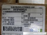
- 10-pin MSOP 118 mil : EM78P143MS10J
Note: Green products do not contain hazardous substances.
|